

The Most Misunderstood Aerodynamic Concepts
|
Getting your Trinity Audio player ready...
|
I have heard from a couple of different pilot examiner friends that there are a number of basic aerodynamic concepts that are often misunderstood by pilot applicants. At the private pilot level, this is disappointing, but may be understandable. What is not understandable or acceptable is seeing a number of their commercial and CFI applicants having little more than a cursory understanding of some of these key concepts. Commercial pilots are seeking to eventually be paid, not only for their flying ability, but also for their knowledge. CFIs are supposed to be the purveyors of knowledge to all of those pilots that come after them. If they don’t have the knowledge to share, the vicious cycle continues.
Baffled by Bernoulli
 A CFI applicant was asked to teach lift during their practical exam. They responded with something about Bernoulli’s Principle creating low pressure on top of the wing. When asked to explain this, the examiner was met with a blank stare. They couldn’t get to or beyond even the basics of the principal.
Daniel Bernoulli was a Swiss mathematician who lived in the 1700s. When he created his principle of differential pressure, he had no thoughts about its future application to the development of airfoils and lift production. Heavier-than-air flight was more than a century away. He died the year before the Montgolfier Brothers sent their first passengers aloft in a lighter-than-air aircraft. Bernoulli’s Principle was put forth in his 1738 book on the properties of fluid flow called Hydrodynamica.
Bernoulli’s Principle states that as the velocity of a moving fluid (liquid or gas) increases, the pressure within the fluid decreases.
This principle can be demonstrated using a device known as a venturi tube. A venturi tube has larger inlet and outlet diameters but has a smaller diameter within the tube that creates a constriction. As a fluid is forced through the tube, the fluid must move faster through the constriction to keep up with the flow of the fluid in the rest of the tube. Due to the conservation of energy, this extra speed doesn’t come out of nowhere. Another factor is changing with the increased speed and that factor is a decrease in pressure. These changes can be demonstrated with the proper measuring equipment on the venturi tube.

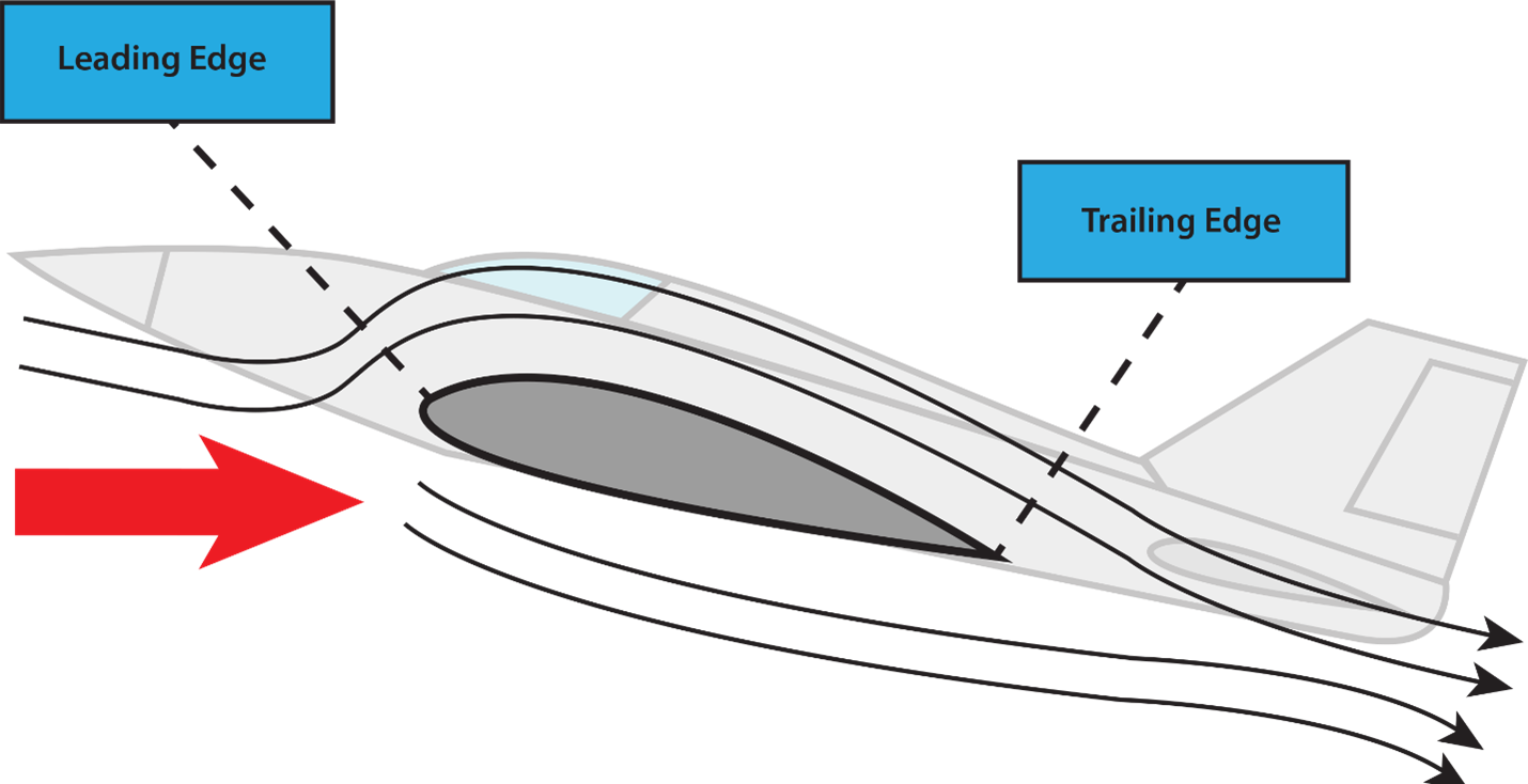
The venturi tube is the start of the explanation, but it doesn’t really show the use of Bernoulli’s Principle in the production of lift without some modifications. First, let’s cut the top off the tube and trim it to the beginning and end of the constriction. With some imagination this looks a bit like the top of an airfoil. Next, instead of forcing the fluid through the tube, let’s force our tube, or at least its bottom half, through the fluid. In the case of our airfoil, we’ll assume that the fluid is air and that the air is relatively still.
As we force the airfoil through the still air, it is separated by the airfoil. Looking at the curvature or camber of a typical general aviation wing, the top has more curvature and thus surface area than the bottom of the wing. Add a bit of angle-of-attack, which moves the separation (stagnation) point vertically down on the leading edge of the wing, and the upper surface area becomes larger. Looking at it from the tip of the wing, the air above the wing has a greater distance to travel to be reunited with the air below at the trailing edge of the wing. This causes the acceleration witnessed in the venturi tube and lowers the pressure on top of the wing.

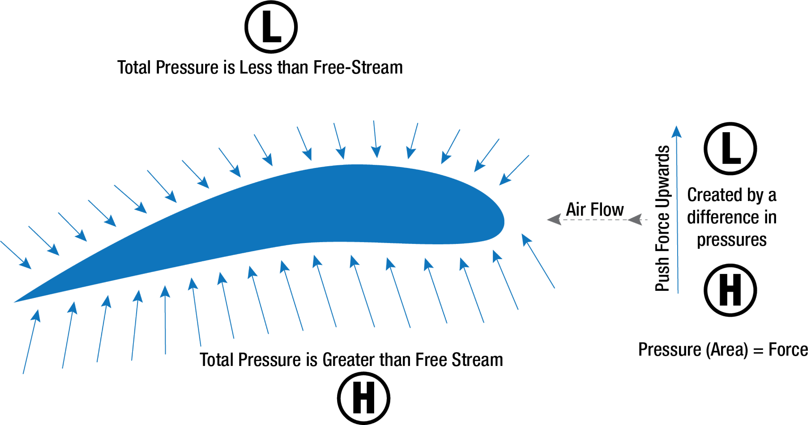
This lower pressure on the top of the wing is a part of the lift production.
Another aspect of the airflow around the wing that must be considered is happening below the wing. At a point close to the leading edge, the airflow is virtually stopped (the previously mentioned stagnation point) and then gradually increases speed. At some point near the trailing edge, it again reaches a velocity equal to that on the upper surface. Applying Bernoulli’s Principle, where the airflow was slowed beneath the airfoil, a positive upward pressure was created. Just like the faster flow, but with the opposite pressure change; as the fluid speed decreases, the pressure must increase. Since the pressure differential between the upper and lower surface of the airfoil increases, total lift increases.
Notorious Newton
 Another pilot applicant was asked about Sir Isaac Newton’s contributions to aerodynamic theories and how they would apply during the flight. The applicant could come up with a couple of Newton’s laws but struggled with the application.
Sir Isaac Newton was an English polymath. He was not only a mathematician, but also a physicist and an astronomer. He also dabbled in theology and alchemy. He wrote his book, Mathematical Principles of Natural Philosophy, approximately 50 years before Bernoulli’s Hydrodynamica. In his book, Newton formulated the law of universal gravitation and also described the three basic laws of motion.
Newton’s First Law: “Every object persists in its state of rest or uniform motion in a straight line unless it is compelled to change that state by forces impressed on it.”
This means that nothing starts or stops moving until some outside force causes it to do so. An aircraft at rest on the ramp remains at rest unless a force strong enough to overcome its inertia is applied. Once it is moving, its inertia keeps it moving, subject to the various other forces acting on it. These forces may add to its motion, slow it down, or change its direction.
Newton’s Second Law: “Force is equal to the change in momentum per change in time. For a constant mass, force equals mass times acceleration.”
When a body is acted upon by a constant force, its resulting acceleration is inversely proportional to the mass of the body and is directly proportional to the applied force. This takes into account the factors involved in overcoming Newton’s First Law. It covers both changes in direction and speed, including starting up from rest (positive acceleration) and coming to a stop (negative acceleration or deceleration).
Newton’s Third Law: “For every action, there is an equal and opposite reaction.”
In an airplane, the propeller moves and pushes back the air; consequently, the air pushes the propeller (and thus the airplane) in the opposite direction—forward. In a jet airplane, the engine pushes a blast of hot gases backward; the force of equal and opposite reaction pushes against the engine and forces the airplane forward.
Looking at our wing again, the air being hit by the bottom of the wing while it moves through the air with a positive angle of attack, gets deflected downward. This creates an equal and opposite reaction to deflect the wing upward creating additional high pressure below the wing.
Newton’s Third Law of Motion is contributing to the total lift on the wing.

Flummoxed by the Flows
Beyond the direct lift created by the high- and low-pressure differentials on the wing, the changes to the air flows imparted by the airfoils create positive and negative lifting effects.
The air flowing across the top surface of the wing imparts a downward direction or downwash to the air. This downwash meets the flow from the bottom of the wing at the trailing edge. Applying Newton’s third law, the reaction of this downward and backward flow results in an upward and forward force on the wing.
At the tips of the wings, the higher-pressure air below the wing tries to spill around the tip to the lower-pressure air above the wing. This spillage is the source of the wing-tip vortices that instructors warn about. Besides being a source of concern when produced by other aircraft, the vortices have a negative impact on the production of lift at the tips of the wings. The vortices produce a downwash, but instead of the downwash pushing down on the air behind the wing, the downwash pushes down on the wingtips themselves. This downwash creates a reduction of lift at the wingtips. Winglets are designed to reduce the spillage from the bottom of the wing to the top of the wing. Reduced spillage produces less downwash on the wingtips. Less downwash directly on the wingtips allows the wingtips to produce more lift, increasing the efficiency of the wing.
Detrimental Drag
Drag is the force that resists movement of an aircraft through the air. There are two basic types: parasite drag and induced drag.
Parasite drag is comprised of all the forces that work to slow an aircraft’s movement. As the term parasite implies, it is the drag that is not associated with the production of lift. This includes the displacement of the air by the aircraft, turbulence generated in the airstream, or a hindrance of air moving over the surface of the aircraft and airfoil. There are three types of parasite drag: form drag, interference drag, and skin friction.
Form drag is the portion of parasite drag generated by the aircraft due to its shape and airflow around it. Interference drag comes from the intersection of airstreams that creates eddy currents, turbulence, or restricts smooth airflow. Skin friction drag is the aerodynamic resistance due to the contact of moving air with the surface of an aircraft.
The second basic type of drag is induced drag. In level flight, the aerodynamic properties of a wing or rotor produce a required lift, but this can be obtained only at the expense of a certain penalty. The name given to this penalty is induced drag. Induced drag is inherent whenever an airfoil is producing lift and, in fact, this type of drag is inseparable from the production of lift. Induced drag is always present when lift is produced.
Recall the downwash into the wingtips produced by the wingtip vortices. Downwash points the relative wind downward, so the more downwash you have, the more your relative wind points downward. That’s important for one very good reason: lift is always perpendicular to the relative wind. When there is less downwash, the lift vector is more vertical, opposing gravity. When there is more downwash, the lift vector points back more, causing induced drag. On top of that, it takes energy for the wings to create downwash and vortices, and that energy creates drag.
The greater the size and strength of the vortices and consequent downwash component on the net airflow over the airfoil, the greater the induced drag effect becomes. This downwash over the top of the airfoil at the tip has the same effect as bending the lift vector rearward; therefore, the lift is slightly aft of perpendicular to the relative wind, creating a rearward lift component. This is induced drag.
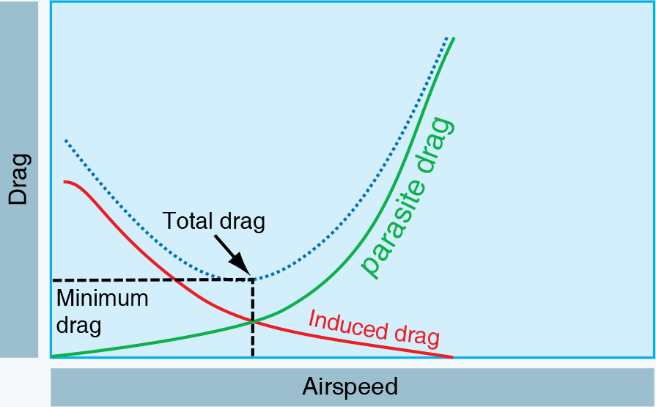
Looking at parasite and induced drag on the same graph:
- As airspeed slows, parasite drag decreases and induced drag increases.
- As airspeed increases, parasite drag increases and induced drag decreases.
- The point where the 2 drag curves cross is the minimum drag possible for the aircraft configuration.
Beyond the Basics
The information presented above should be considered as a basic understanding of some aerodynamic concepts. Aerodynamics is a much more in-depth subject than will be covered in FAA handbooks and a simple blog post. Many engineers spend a lifetime studying and improving on the subject.
Some additional “pilot level” study might include a review of a few formulas that are found in the Pilot’s Handbook of Aeronautical Knowledge related to lift and drag.
The coefficient of lift (CL) is defined as “The ratio between lift pressure and dynamic pressure.”
Lift can be calculated using the lift formula.

It should be noted that since velocity is squared, if all other factors remain equal, doubling the velocity of the wing will quadruple the lift.
Inevitably, doubling the velocity and quadrupling the lift is only possible as a mathematical formula. An aircraft could not continue to travel in level flight at a constant altitude and maintain the same AOA if the velocity is increased. The lift would increase and the aircraft would climb as a result of the increased lift force or speed up. Therefore, to keep the aircraft straight and level (not accelerating upward) and in a state of equilibrium, as velocity is increased, lift must be kept constant. This is normally accomplished by reducing the AOA by lowering the nose. Conversely, as the aircraft is slowed, the decreasing velocity requires increasing the AOA to maintain lift sufficient to maintain flight. There is, of course, a limit to how far the AOA can be increased, if a stall is to be avoided.
Drag can be calculated using a similar formula with the difference being that a coefficient of drag is used.

Doubling velocity in this formula would quadruple the drag.
The lift-to-drag (L/D) ratio is determined by dividing the CL by the CD, which is the same as dividing the lift equation by the drag equation as all of the variables, aside from the coefficients, cancel out.
An element of both equations is dynamic pressure. Dynamic pressure is often expressed as “q” where:

The L/D ratio is the amount of lift generated by a wing or airfoil compared to its drag. A ratio of L/D indicates airfoil efficiency. Aircraft with higher L/D ratios are more efficient than those with lower L/D ratios. In unaccelerated flight with the lift and drag data steady, the proportions of the CL and CD can be calculated for specific AOA as shown in the graph below.
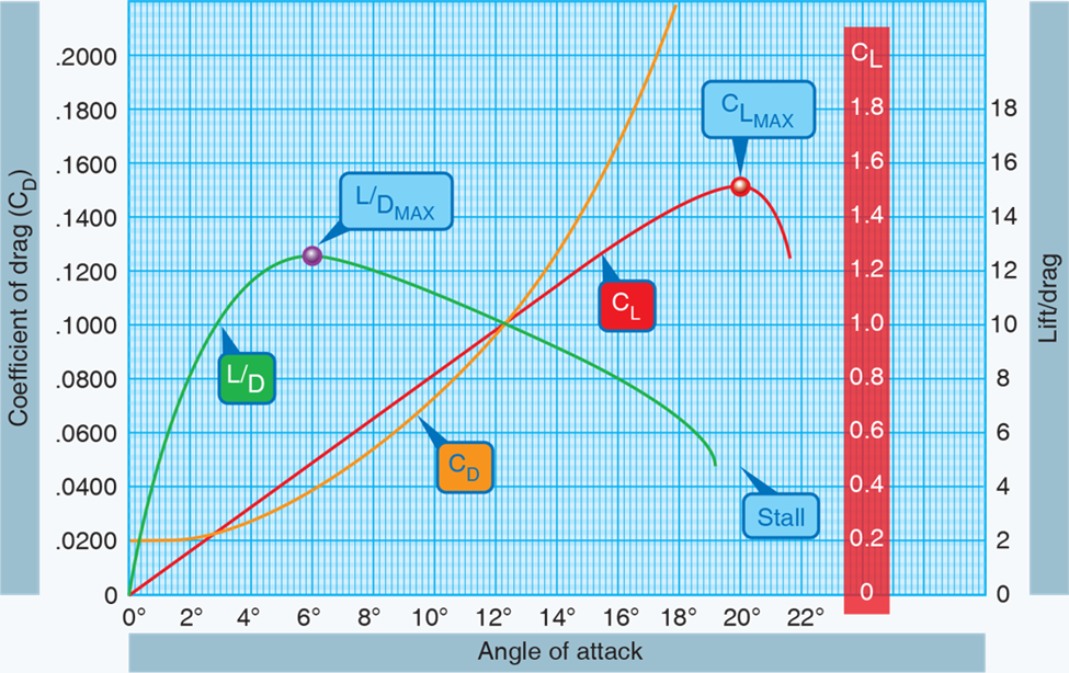
Notice that the coefficient of lift curve (red) reaches its maximum for this particular wing section at 20° AOA and then rapidly decreases. 20° AOA is therefore the critical angle of attack. The coefficient of drag curve (orange) increases very rapidly from 14° AOA and completely overcomes the lift curve at 21° AOA. The L/D ratio (green) reaches its maximum at 6° AOA, meaning that at this angle, the most lift is obtained for the least amount of drag.
Note that the maximum lift/drag ratio (L/DMAX) occurs at one specific CL and AOA. If the aircraft is operated in steady flight at L/DMAX, the total drag is at a minimum. Any AOA lower or higher than that for L/DMAX reduces the L/D and consequently increases the total drag for a given aircraft’s lift.
Conclusion
Having at least a basic understanding of aerodynamics is important for all pilots and it will be evaluated on the practical exam for a certificate or rating. The further along a pilot is in their certificates, the more advanced their understanding of aerodynamics should be. Pilots should take the time to study this information and be prepared for the practical exam along with being prepared for flight situations that will test the application of their understanding.
Fly and stay safe!
Now Let’s Test Your Understanding of These Aerodynamic Concepts!


In his role as VP of Safety, Security, and Compliance for Sporty's Academy, Chief Jurgens develops and maintains the necessary systems to fulfill that role. He also develops material which eventually becomes a part of the courseware used at Sporty's Academy and sold through Sporty's Pilot Shop.
- Common Aircraft Fuel Myths - January 5, 2026
- Distractions on the Ramp: How a Moment’s Inattention Can Cost Lives - October 27, 2025
- MOSAIC Rule Explained: New Sport Pilot Privileges and LSA Standards - September 29, 2025
We need to teach uncomplicated concepts to start. More in depth understanding will come as a students experience grows and more can be taught
This is simply the best exposition on Bernoulli and lift I have ever read. The explanations are cleat and straightforward, the mathematics is accessible (I have a master’s degree in epidemiology/biostatistics), and the quiz wraps it all together. I will use this article in my high school aviation STEM camps in the coming year. Thank you, Paul Jurgens.
Excellent presentation with clear figures. As a retired Mechanical engineer familiar with fluid flow, and a pilot I enjoyed the presentation and learned a better method to explain these incredably important concepts. Thanks!
It is really unfortunate to see an article that starts by complaining that CFI candidates don’t understand where lift comes from but then proceeds to repeat the incorrect “air travels faster over the top surface because it has further to go” basis for applying Bernoulli’s principle that likely contributes to the ongoing lack of understanding. It simply is not true. If one tracks the actual motion it is easy to demonstrate that the air passing over the upper surface arrives “late” and does not meet up with the corresponding packet that passed under the wing. Also, there is no reason to expect or require it to do so. If you cut open a Venturi tube you totally change the conditions of the experiment and the analysis does not hold. To exert a force you need to change momentum (Newton rules!) and it is the redirected airflow that generates the lift. Sorry.
I agree. The equal transit time theory is hogwash. In fact, wind tunnels show the airflow over the top of the wing reaches the trailing edge before the flow from the bottom of the wing. And, like Dominic said, the wing is not a Venturi because there is no restriction above the upper surface of the wing.
I agree that by altering the original experiments parameters you alter the results
This is so wrong. Not the explanation about Bernoulli’s principle, but insisting in teaching that it is the main factor by witch a wing foil produces lift. The irony is in how the article starts criticizing exactly what it is doing!! To then go to the same misconception. Many airplanes have wing folks that are simetric (exactly same curvature profile on both , upper and lower side of the foil.
The major factor producing lift is THE ANGLE OF ATTACK. PERIOD!!!
You can make a model airplane with just flat pieces of cardboard and it will fly fine.
Take your hand out of your car window, put it flat perpendicular to the the air flow (like cutting it) and just tilt it a bit (add some ANGLE OF ATTACK). Can you feel the force of lift ? Did you change the profile of your hand to feel that ? Did you make the top surface “longer” than the bottom surface of your hand?
Yes . Bernoulli principle is there in a wing but by no means is the reason why a wing produces lift.
Reading the intro of this article I had hope of getting a good explanation on how this misconception gained so much traction that is taught like a dogma (just believe and repeat) to find it doubling down on the dogma. Nothing wrong with all the details on how bernoulli principle on an asimétrico airfoil works, but is NOT the main reason why the airfoil produces lift that is the exact point the article started to challenge .
How can we really stop this snowball of misconception being taught and repeated and cemented as the absolute true .
If it where true, instead of having flaps or ailerons as surfaces selectively changing the angle of attack (to selectively increase/decrease the lift, we should have mechanisms to change the profile of the wing (inflate/deflate the top of the wing surface) to increase/decrease the Bernoulli effect, hence increasing/decreasing lift. Wrong.
“Induced drag is always present when lift is produced” except that an infinite span has no induced drag when lift is produced. This concept is important in understanding aspect ratio and L/D.
Thank you for cutting through that explanation , in fact your explanation of angle of attack using, the hand out the car window, is so understandable and reduced his explanation, and made easier to remember in concept, for a learning student thank you
This was a more enjoyable and comprehensible read for me now that I’m an instrument-rated private pilot with 200 hours under my belt. Attempting to understand the totality of these concepts as a novice pilot is, in my view, not a good use of time. Sure, it is academic knowledge that CFIs should be able to teach their students, but I can think of a host of other topics that would contribute to safer flight in GA pilots (learning more about the mechanics of the onboard systems in a single-engine plane could go a long way in spotting mechanical issues earlier, for example). Not being a student of any sort of physics, I found other comments on lift generation interesting and informative, namely that angle of attack has a much greater effect on generating lift.
I’ve bumped into a few outdated concepts in my short time as a pilot. As an example, I listened to an interview with an AME (Aviation Medical Examiner) who was explaining that the oxygen rules were established based on science from the 50s and haven’t been updated since. I’m paraphrasing here, but he was implying that a pulse oximeter is the most reliable tool for knowing when oxygen is required due to blood oxygen saturation levels differing person by person based on their physical condition, age, etc, as well as what altitude they are acclimated to. I’m sure it’s not a priority for the FAA, but I’d love to see some topics be updated with modern science and I’d love to see less bashing of students for not remembering equations about the coefficient of lift; I really feel it’s more helpful for folks to dedicated limited brain space to practical matters, like how to taxi in wind.
Nevertheless, thank you for the clear explanation of a complicated subject that I’m now more capable of understanding.
Like some of the other commenters, I want to also reiterate my disappointment that someone bashing those that teach lift wrong starts with the suggestion that “air above the wing has further to travel to reunite with the air under the wing” nonsense.
Back in the 1990’s my favourite forum during AirVenture was the argument between the Newtonians and Bernouillians about which explanation of lift was better. Basically, it was physicists versus engineers. The former benefited from the easier explanation of lift, while the latter had access to equations that simplified wing design. As a chemist, and I suppose an Avogadran, I felt that my guy was being ignored both. Leaving that aside, I found the best way explain lift to student pilots and kids was to start with Newton using a snowplow blade which was gradually angled forward. Snow is still piling up in front (of the wing), while the back of the blade (the top of the wing) is going away. Then demonstrate Bernoulli by blowing on a sheet of paper dangled over the top of a book. Since the book is blocking any blown air from going under the paper, air pressure below is unchanged, but the rising page demonstrates lower pressure above it.
You really should take this page down. As noted by several others, Bernoulli is not why wings produce lift, and Sportys should not be one to continue pushing this fallacy. (If Bernoulli had much of anything to do with it, flat winged planes such as most fighter jets, and most paper airplanes, would not be able to fly.)
Paul, this was very good article about creation of lift, thank you very much. I agree that many Designated Pilot Examiners (DPEs) do focus on aerodynamic theory during their evaluations.
I am a mechanical engineer with 55 years of flying experience. Upon retiring from flying USAF fighters, I was taking my Air Transport Pilot checkride from the late, great DPE Jim Walden, about 25 years ago. Weather was crappy, well below minimums, which gave Jim extra hours to quiz me during the oral exam. When he asked about “lift,” I went into a discussion on Bermoulli and Newton (we weren’t talking much about Coanda back then). Jim immediately stopped me by saying “No, Bernoulli was just a plumber” who was was working to help Italian plumbers make shi, oops I meant sewage, flow downhill more efficiently. The remainder of our discussion on aerodynamics focused not on the theory of lift, but how the pilot CONTROLS lift!
I passed the checkride and never used my ATP certificate, but have used his rationale ever since while teaching students.
I try to focus on aerodynamic concepts that can benefit the pilot with aircraft control, not focus on things that the pilot cannot control.
Pilots only use their left hand, right hand, and feet to control the airplane. They control total energy using their throttle hand and control angle of attack using their yoke/stick hand and their feet. Pilots cannot control air density (except by refusing to fly if density altitude is too high) or wing area (I used to be able to do this with a wingsweep handle and huge double-slotted Fowler flaps). Therefore, we drop down to angle of attack (directly proportional to Coefficient of Lift) and airspeed (pick any type you want, KTAS/KCAS/KIAS) squared.
Reading numerous fatal mishap reports (especially stall/spin, maneuvering flight, loss of control-inflight), reveal a misunderstanding by pilots on how the elevator (control yoke/stick) position affects aircraft control.
The FAA’s, 41 page, 1955 “Facts of Flight” emphasized the purpose of the Elevator was to control angle of attack. Today, the 406-page Airplane Flying Handbook, the 522-page Pilot’s Handbook of Aeronautical Knowledge, and the 23-page AC 61-67C “Stall Spin Awareness Training only casually mention (buried in the middle of everal long paragraphs) the relationship between AoA and elevator/stick position. My Univ of Cincinnati Aeronautical Professor friend alludes this change is probably because aerodynamic engineers still cannot agree on how to control lift.
I feel it is much more important to focus pilot training on the aerodynamics of “controlling” the airplane and leave the aerodynamics of building the airplane to the engineers.
When I listened to your article, I learned a new word, “oh-ah” for angle of attack, or “alpha.”
Paul, please watch the Secret of Flight 2 video on YouTube (you should watch them all) and you will plainly see that the airflow over the top of the wing reaches the trailing edge BEFORE the airflow under the wing. You can skip to about the twenty minute point if you’re in a hurry. These videos are 70+ years old, so this phenomenon was known well before that. I don’t know how the equal travel time theory was ever put in FAA handbooks and how it has survived this long.
https://www.youtube.com/watch?v=6RIvt2sbEaY
To Michael Reid’s point,
A diagram showing the smoke tunnel “streamline” visualization at zero AOA in which the slipstream streamlines compress together as the (incompressible) air accelerates over the upper curved airfoil surface while the slipstream streamlines over the relatively flat bottom surface remain widely spaced and do not accelerate above free stream, would help. Note that this phenomenon is exaggerated inside a ventury, but it also occurs in free stream air without constricting ventury walls as well.
Enjoyed the article and comments!